• Products
  • Solutions
  • Support
  • Contact
  • Order OnlineOrder Online

What Is a Three Phase Meter and How Does It Work?

A three phase meter measures electrical energy across three alternating-current conductors, commonly separated by 120 electrical degrees. It is widely used in factories, commercial buildings, data centers, and large workshops. Unlike a single-phase meter, it observes voltage and current on each phase, then combines their power readings over time. The result appears in kilowatt-hours, often with demand, power factor, and phase-balance information.

The need for accurate measurement is growing. The International Energy Agency’s Electricity 2024 report projects global electricity demand growth of about 3.4% annually from 2024 to 2026. More connected equipment makes dependable metering increasingly important. A practical example is a motor panel: three current transformers surround the incoming conductors, while voltage leads connect to the meter’s sensing circuit. The meter samples both signals, calculates real power, and accumulates energy continuously. Small errors matter.

Modern meters may use direct connections for modest currents or current transformers for higher industrial loads. Their accuracy and testing requirements are addressed by international standards, including IEC 62052-11 and IEC 62053-22. These standards help manufacturers and inspectors evaluate performance under defined electrical conditions. Still, a compliant device can produce misleading results when transformers are incorrectly sized, phases are reversed, or connections are loose. Installation quality matters as much as the display.

This guide explains what a three phase meter is, how its internal measurement process works, and where readings can fail. It also considers billing, monitoring, safety, and maintenance. The technology seems straightforward. Real systems are not. Understanding the details helps engineers, facility managers, and buyers choose equipment with greater confidence.

What Is a Three Phase Meter and How Does It Work?

What Is a Three-Phase Meter?

What Is a Three-Phase Meter?

A three-phase meter measures electrical energy in systems using three alternating-current phases. These phases are separated by about 120 degrees, creating a smoother power supply for large equipment. Factories, workshops, commercial buildings, and some larger properties commonly use this arrangement.

The meter samples voltage and current on each phase. It then calculates power and records energy use in kilowatt-hours. Many models also show voltage, current, power factor, and phase imbalance. Current transformers may be used when the electrical load is too high for direct connection. In practice, an electrician checks phase order, wiring, and meter settings before trusting the readings. A small connection error can produce confusing results. It is easy to assume the meter is faulty, but uneven loads often cause the problem.

Tips: Keep the meter cabinet dry and accessible. Compare the three phase readings regularly. Large differences may indicate an overloaded circuit, loose connection, or equipment issue. Never open an energized panel. A qualified electrician should test wiring, confirm calibration, and investigate unusual readings with proper instruments.

What Is a Three-Phase Meter and How Does It Work?

Data Dimension Typical Information How It Relates to the Meter
Definition An electrical measuring device for three-phase systems Measures electrical quantities across three alternating-current phases.
Number of Phases Three AC phases, normally separated by 120 electrical degrees The meter samples each phase and combines the results to determine total system performance.
Common System Configurations Three-phase, three-wire; or three-phase, four-wire with a neutral conductor The meter must match the wiring arrangement and system voltage.
Measured Voltage Line-to-line voltage and, where a neutral is present, line-to-neutral voltage Voltage channels monitor the potential difference between selected conductors.
Measured Current Current in each of the three phase conductors Current inputs may be direct-connected or connected through current transformers for larger loads.
Frequency Typically 50 Hz or 60 Hz, depending on the electrical grid The meter uses the alternating waveform to calculate frequency and synchronize voltage and current measurements.
Active Power Measured in watts (W) or kilowatts (kW) For a balanced system, active power can be estimated as √3 × line voltage × line current × power factor.
Reactive Power Measured in var or kilovar (kvar) Indicates energy that moves between the source and inductive or capacitive loads.
Apparent Power Measured in volt-amperes (VA) or kilovolt-amperes (kVA) Represents the combined effect of voltage and current and is useful for evaluating equipment loading.
Power Factor A dimensionless value from 0 to 1 for typical loads Shows how effectively apparent power is converted into useful active power.
Energy Measurement Usually recorded in kilowatt-hours (kWh) The meter integrates active power over time to calculate consumed or exported energy.
Measurement Principle Digital sampling of voltage and current waveforms A processor calculates RMS values, phase relationships, power, and energy from sampled signals.
Phase Sequence The order in which the three phase voltages reach their cycle positions Correct phase sequence is important for motor rotation and accurate system monitoring.
Phase Balance Comparison of voltage and current among the three phases Unequal readings can indicate uneven loads, wiring problems, or supply abnormalities.
Typical Applications Commercial buildings, industrial facilities, distribution panels, and large electrical equipment Three-phase meters are suited to installations with substantial or continuously monitored electrical loads.
Key Installation Requirement Correct voltage rating, current rating, wiring configuration, and phase identification Incorrect connections can produce inaccurate readings and may create electrical safety hazards.

Key Components of a Three-Phase Meter

What Is a Three-Phase Meter and How Does It Work?

Key Components of a Three-Phase Meter

A three-phase meter measures voltage, current, power, and energy across three electrical phases. Its current transformers reduce heavy line currents to safe measurement levels. Voltage sensors perform a similar task for phase-to-phase or phase-to-neutral voltage.

Inside, an analog-to-digital converter samples these signals many times per cycle. A processor then calculates active, reactive, and apparent power. It also checks power factor, phase sequence, and phase imbalance. The terminal block holds the incoming and outgoing conductors securely. Insulation barriers separate dangerous circuits from low-voltage electronics.

Communication hardware sends readings through wired networks, radio, or cellular links. A local display shows energy use, alarms, and sometimes demand peaks. The enclosure protects these parts from dust, vibration, and accidental contact. Small details matter.

The U.S. Energy Information Administration reported more than 120 million advanced meters in service in recent annual data. This scale shows why accurate measurement supports modern grid operations. IEC 62052 and IEC 62053 define important requirements for meter safety, testing, and accuracy. However, real installations still face heat, harmonics, loose connections, and incorrect phase wiring. A meter can calculate perfectly and still report poor data when installation work is careless. That practical weakness deserves more attention.

What Is a Three-Phase Meter and How Does It Work?

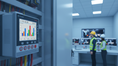
A three-phase meter measures electrical values on phases L1, L2, and L3. The chart below compares typical balanced three-phase readings, including line-to-neutral voltage, current, and power factor.

A three-phase meter uses voltage and current sensors on each phase. Its internal electronics calculate values such as voltage, current, power factor, active power, and energy consumption. Similar readings across all three phases indicate a well-balanced load.

How a Three-Phase Meter Measures Electricity

A three-phase meter measures electricity by sampling voltage and current on three separate conductors. Each phase is normally separated by about 120 electrical degrees. Inside the meter, voltage sensors and current transformers capture changing waveforms many times per second. Digital circuits then multiply each voltage sample by its matching current sample. The meter adds the three results to calculate total real power. It integrates that power over time and records kilowatt-hours. For a balanced load, engineers may use P = √3 × V × I × power factor. Real installations are rarely perfectly balanced.

Power factor matters. A motor can draw substantial current while producing less useful power than expected. The meter detects this phase relationship and can record active, reactive, and apparent energy. IEC 62053-22 defines performance requirements for transformer-operated active-energy meters, including accuracy classes such as 0.5S and 1.0. In practice, technicians compare readings with calibrated test equipment, inspect current-transformer polarity, and check loose connections. Small wiring errors can create large billing or monitoring errors. A practical warning: a stable display does not prove a correct measurement. The IEA’s Electricity 2024 report recorded global electricity-demand growth of 2.2% in 2023 and projected average annual growth of 3.4% through 2026. As consumption rises, reliable phase-by-phase data becomes more valuable. Yet no meter is perfect; harmonics, temperature, sensor aging, and poor installation can reduce accuracy. (Sources: IEC 62053-22; IEA, Electricity 2024; U.S. EIA, Electric Power Monthly.)

Types and Applications of Three-Phase Meters

What Is a Three Phase Meter and How Does It Work?

A three-phase meter measures voltage, current, power, and energy across three alternating-current phases. Each phase reaches its peak at a different time, creating a smoother power supply. The meter samples these electrical values, calculates real power, and records consumption in kilowatt-hours. In practical installations, it must match the system voltage, frequency, wiring arrangement, and load capacity. A neat digital display does not prove accurate measurement. Incorrect wiring can still produce believable readings.

Types and Applications of Three-Phase Meters

Direct-connected meters suit smaller commercial panels where the current stays within the meter’s rated limit. Larger facilities often use current transformers, which reduce high current to a measurable level. Digital meters provide clearer readings and may track demand, power factor, voltage imbalance, and peak consumption. Smart models can transmit data for remote monitoring, while basic meters remain useful for local checks. Common applications include factories, office buildings, workshops, apartment blocks, renewable-energy systems, and charging areas. Balanced loads are easier to assess. Uneven loads need closer attention because one phase may overheat or waste energy.

Tips: Confirm the phase sequence before commissioning. Compare readings with a calibrated tester when possible. Inspect terminals for heat marks, loose screws, or damaged insulation. Keep records during similar operating periods. This helps reveal unusual demand. I have found that one reading rarely tells the whole story. Load conditions change, and meters can expose patterns that simple monthly totals hide. Always follow qualified electrical procedures and applicable local standards.

How to Read and Maintain a Three-Phase Meter

A three-phase meter measures electrical energy across three alternating-current phases. It records voltage, current, power factor, and total consumption, usually in kilowatt-hours. Reading one requires attention, not guesswork. Check the unit before recording anything. A value in kWh shows energy use, while amperes indicate current on each phase. Many digital meters rotate through several screens automatically. Wait for the display to return to the energy reading.

Write down the date, time, and displayed value. Compare all three phase readings when the meter provides them. Large differences may suggest uneven loads, a faulty connection, or unusual equipment demand. Do not assume the highest number means failure. Operating schedules can change the result.

A simple inspection also matters. Look for cracked covers, moisture, heat marks, damaged cables, or a loose display. Keep the area dry and unobstructed.

Never remove a sealed cover or touch energized terminals.

Qualified electrical personnel should test connections and confirm calibration. They can use approved instruments and follow local safety requirements. Maintenance records should include readings, inspection dates, faults, and corrective work.

Small details are easy to miss. I have found that rushed readings often create bigger problems later. Recheck unusual values before reporting them, but do not delay professional help when burning smells, smoke, or exposed conductors appear.