X
X
X
X Choosing a split core current sensor in 2026 is not just a matter of matching an ampere rating. The sensor must fit the conductor, measurement range, installation method, and monitoring equipment. It should also suit the actual conditions inside the panel. Tight spaces matter. So does a jaw that does not close fully.
The International Energy Agency’s Electricity 2025 report says global electricity demand grew by 4.3% in 2024, with further growth expected through 2027. That figure does not measure sensor sales. It does show why dependable current monitoring matters across buildings, industry, and power systems. As loads change, poorly matched sensors can produce readings that mislead operators or weaken energy analysis.
This guide explains how to compare sensor types, current ranges, accuracy specifications, output signals, and safety ratings. Check whether a model uses current-transformer or Hall-effect technology; their operating requirements differ. Confirm the conductor diameter and available clearance before ordering. Then review low-current performance, frequency response, and compatibility with your meter or control system. A datasheet helps, but it cannot reveal every installation problem. That part deserves a real check.
One uncomfortable truth: “easy to install” does not mean “easy to specify.” A sensor may fit the cable yet perform poorly at the load levels you actually measure. This guide offers a practical selection process, while leaving room to question assumptions and verify critical specifications with the manufacturer.
How to Choose a Split Core Current Sensor in 2026?
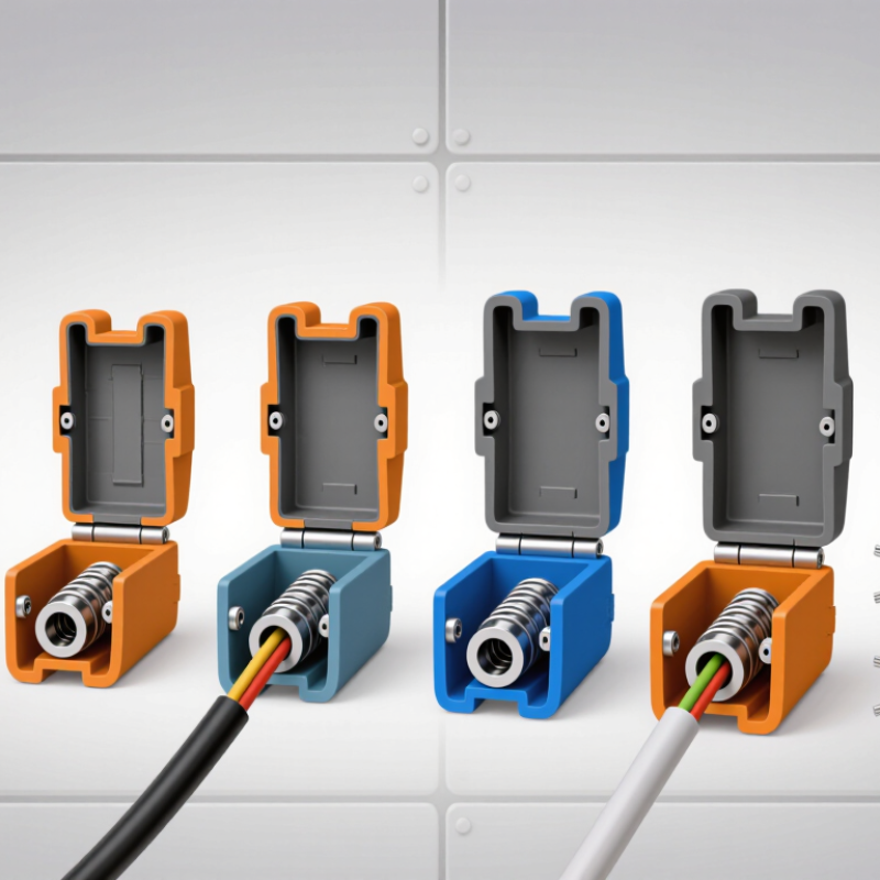
A split core current sensor uses a hinged magnetic core to measure current without disconnecting the conductor. When the core closes around an AC-carrying wire, the wire acts as a primary winding. Magnetic flux induces a proportional signal in the sensor’s secondary winding. The output may be a current or voltage, depending on the design.
That matters. A visible latch is not proof of a fully closed core. Dust, a trapped cable tie, or slight misalignment can leave a gap and affect accuracy. Small gaps matter. During installation, center one conductor inside the opening; enclosing both outgoing and return wires can cancel their magnetic fields. Standard current-transformer designs also do not measure steady DC directly.
The operating principle is only part of the selection. Check the rated current, output type, frequency range, accuracy, and permitted secondary burden. A sensor nearing its current limit may saturate, so allow headroom for expected peaks. Also confirm that the opening fits the cable and that the insulation rating suits the installation. Check the data sheet. A practical bench check with a known AC load can reveal wiring or configuration errors, though it cannot replace calibrated testing when precise measurement is required.
Idealized response for a 1,000:1 current transformer with a 10 Ω burden resistor and one primary pass through the core.
With these assumptions, secondary current is primary current divided by 1,000, and burden voltage is secondary current multiplied by 10 Ω. The plotted values follow this ideal relationship; actual sensor accuracy and usable range depend on core design, frequency, burden, and saturation limits.
Before selecting a split core current sensor, define what the measurement must show. Are you checking a steady motor load, capturing startup peaks, or monitoring an intermittent circuit? These needs affect the required current range, response, and recording interval. Write down the normal operating current and the highest credible peak. A clamp meter reading during one quiet moment is not enough.
Choose a range that covers expected peaks without sacrificing useful resolution at normal load. For example, a sensor sized for several hundred amps may make small changes harder to distinguish on a lightly loaded circuit. Check the instrument’s stated accuracy across its full range, not only at one test point. Also confirm whether accuracy is specified as a percentage of reading or full scale. That distinction matters.
Consider the conductor size and installation space, too. The core must close fully around the cable; a small gap can undermine a reading. Verify that the sensor supports the conductor’s insulation and the measurement setup. For AC measurements, note the frequency range. For pulsed or changing loads, check response time and peak capture. These specifications can look neat on paper. Real panels are less tidy, and I would leave some margin rather than assume every load behaves as expected.
| Example application | Expected current | Range to consider | Current type and sensor | Typical output option | Aperture check | Measurement target | Selection note |
|---|---|---|---|---|---|---|---|
| Small branch-circuit load monitoring | 5–30 A RMS | Approximately 0–50 A AC | AC; split-core current transformer (CT) | Low-level AC current or voltage output | Measure the insulated conductor diameter and allow room for installation. | Around ±1–2% of reading across the normal operating range | Choose a range close to the expected load; an unnecessarily large range can reduce useful resolution. |
| Equipment feeder monitoring | 20–100 A RMS | Approximately 0–150 A AC | AC; split-core CT | Voltage output or secondary current output, matched to the meter input | Check the core opening against the largest conductor or cable bundle to be measured. | Around ±1% of reading where energy or load comparisons require improved repeatability | Confirm the sensor’s rated output and burden are compatible with the connected instrument. |
| Commercial building distribution panel | 50–250 A RMS | Approximately 0–400 A AC | AC; split-core CT | Voltage output or 1 A / 5 A secondary, if supported by the measurement system | Verify clearance around busbars and nearby phases before selecting the core shape. | Typically ±1–2% of reading for general monitoring; verify the full accuracy specification. | Check rated frequency, phase spacing, installation access, and the system’s maximum current. |
| Motor or pump feeder with startup current | 40–200 A RMS in operation; brief startup peaks may be higher | Approximately 0–600 A AC, subject to peak duration and waveform | AC; split-core CT with suitable transient capability | Output compatible with the recorder or protection input | Allow for the cable’s outside diameter, bends, and installation clearance. | Set accuracy needs for steady-state readings; separately verify peak response and saturation limits. | Do not size from running current alone. Check inrush magnitude, duration, and sensor response time. |
| Large feeder or busbar monitoring | 200–800 A RMS | Approximately 0–1,000 A AC | AC; large-aperture split-core CT | Low-level voltage or current output selected for the receiving device | Measure busbar dimensions and check whether the core can close fully around it. | Often ±1–2% of reading for monitoring; tighter targets require application-specific verification. | Confirm maximum continuous current, thermal limits, insulation rating, and available installation space. |
| Battery, inverter, or DC bus monitoring | 50–300 A DC, possibly with AC ripple | Approximately 0–400 A DC | AC/DC; split-core Hall-effect sensor | Analog voltage or current output; check supply and zero-current offset | Check conductor size and ensure the split core closes without obstruction. | Around ±1–2% of reading may be a practical target; verify offset and temperature effects. | A conventional CT cannot measure steady DC. Confirm the Hall sensor’s DC range, bandwidth, and power requirements. |

| Selection checklist: define AC or DC, normal RMS current, maximum continuous current, peak or inrush current, frequency or bandwidth, required accuracy, output type, conductor dimensions, and installation conditions. For a CT with a current-output secondary, follow the manufacturer’s safety instructions; never leave an energized CT secondary open-circuited. | |||||||
Matching Sensor Output, Accuracy, and Electrical Compatibility
Start with the signal your meter or controller accepts: milliamps, volts, or a current output such as 1 A or 5 A. A mismatch can overload an input or produce misleading readings. Check the sensor’s output range, supply needs, and wiring diagram before installation. Small details matter.
Accuracy must fit the job, not just look impressive on a datasheet. IEC 61869-2 defines accuracy classes for instrument transformers, but performance depends on specified current ranges and burdens. Compare the class at your actual operating current, especially when loads vary overnight. A sensor rated for high-current accuracy may be less precise at low loads. Test it against a trusted reference if the readings seem odd.
Also confirm conductor size, frequency, insulation rating, and available clearance. The U.S. Energy Information Administration reports that electricity delivery losses averaged about 5% in the United States from 2018 to 2022; sound measurement helps operators understand where energy is used, though a sensor alone cannot reduce losses. Check whether the split core closes fully around the cable. Dust or a pinched lead can leave a gap. Fit matters. A tidy specification match can still disappoint in a crowded panel, so verify the installation conditions before ordering.
Before selecting a split core current sensor, measure the actual installation space. A panel drawing may not show crowded cable ducts, nearby terminals, or a door that swings inward. Leave room to open the sensor and close its latch without forcing either part. A tight fit can make later inspection frustrating.
Check the conductor’s outside diameter, including insulation, and compare it with the sensor’s opening. Allow for the cable’s natural bend; a sensor that fits on paper may press against a sharp bend in the cabinet. Small detail. Also check whether the sensor can be installed without disconnecting the conductor. That matters when access is limited, though it should not replace safe work procedures.
Environmental conditions deserve the same attention as dimensions. Note the expected temperature range, humidity, dust, vibration, and possible condensation near the installation point. A sensor mounted beside a warm drive or in a damp service area may face conditions unlike those in a clean control room. Check the product’s stated operating limits and enclosure protection, rather than guessing from appearance. I have seen planning focus heavily on current range and overlook access for the latch. That is an easy omission, and not every site layout is as tidy as its drawing suggests.
A split core current sensor should be judged by its documented limits, not just its stated accuracy. Check the rated voltage, current range, frequency, and measurement category against the actual installation. Confirm that its insulation and enclosure suit the location, especially where dust, moisture, or heat may be present. Ratings matter. A split core can simplify installation, but it does not make work on an energized conductor automatically safe. Follow site procedures and verify that the sensor closes fully around the conductor.
Calibration details deserve equal attention. Look for a stated accuracy across the current range you expect to measure, not only at one convenient test point. Ask whether calibration records identify the method, date, and traceability of the reference equipment. A sensor used mostly at low loads may perform differently from one operating near its rated range. Check the fit. A small air gap, misaligned core, or trapped grit can affect readings, and installation notes are easy to overlook.
Long-term performance depends on the conditions around the sensor. Repeated temperature swings, vibration, and poor cable support can contribute to drift or intermittent readings. Compare readings with a trusted reference during commissioning, then set a review interval based on operating conditions and measurement importance. Small details count. No interval suits every site; that uncertainty should be recorded rather than hidden. Keep calibration results and installation changes together, so future checks can distinguish sensor drift from a changed conductor or load.